Loading...

MbDFEM Simulation of the Oblique Pin Pendulum.

Problem description.

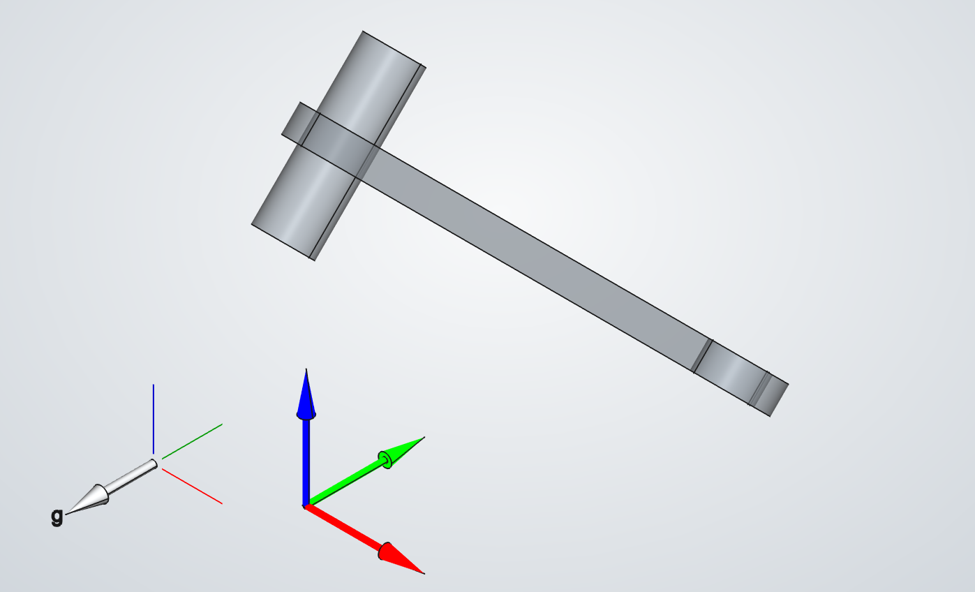
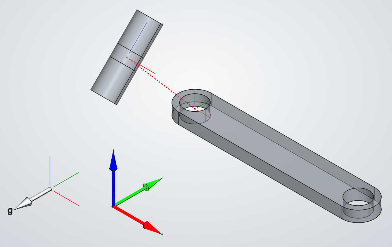
In our Simple Pendulum example, the direction of the hinge joint Z axis (the rotation axis), was perpendicular to the gravity vector. Thus, the hinge joint torque was zero, and there were no FEM loads derived from joint torque. In this example, the pin is rotated 45 degrees about global X. The image on the left shows the exploded assembly of this new configuration. The image below shows the solved assembly. The direction of gravity is shown in both images. The dimensions of the parts are the same as in the Compound Pendulum simulation.

MBD SIMULATION.

This change in the initial assembly means that:

  • The joint reaction force becomes oblique.
  • The joint reaction torque is no longer zero.

The video on the left shows an animation of the pendulum free body diagram. The body weight vector and the d'Alembert force and torque are shown at the pendulum center of mass. The joint force and the joint torque vectors are shown at the hinge joint position (center of the hole). Force vectors in red. Torque vectors in blue.

MbD solver main settings.

  • Initial time: 0.0 [s].
  • Final time : 0.897 [s].
  • Time step: 0.003 [s].

FEM input.

In total, there are four FEM loads distributed among four sets of FEM nodes:

  • Axis FEM load from AxialForce component.
  • Side FEM load from SideForce component.
  • FEM load from joint torque, on pressure side one.
  • FEM load from joint torque, on pressure side two.

The video on the left shows the distribution of these four FEM loads among the FEM nodes. Gravity and d'Alembert acceleration vectors are also shown at the center of mass of a set of FEM volume elements.

To compute the SideForce and AxialForce, the JointForce vector is resolved into its side and axial components. The AxialForce is parallel to the hinge Z axis (the pin axis). The next relation is satisfied:

JointForce = SideForce + AxialForce.

The video on the left shows the JointForce and its SideForce and AxialForce components. The force vector is depicted by the continous red line. Its components are represented by the red dashed lines.

The video on the left shows a close-up of the SideForce and AxialForce FEM loads.
The video on below shows a close-up of the two FEM loads derived from joint torque.

SIMULATION RESULTS.

In the previous videos, the FEM load vectors derived from joint force (AxisForce and SideForce), were scaled-up using a scale ten times higher than the one used in the visualization of the FEM loads from joint torque. This is because the joint torque leads to much higher FEM loads than those from joint force. As consequence, the stresses generated by the torque become dominant over the stresses from joint force. This is a direct consequence of the torque arm: the displacement vector from the pendulum center of mass to the hinge position.

Since the joint torque vector is constant in the reference frame of the pendulum, and the stresses generated by the torque are predominant, the stress induced in the pendulum is principally the stress from torque, and this stress is esentially the same throughout all the pendulum motion. This can be appeciated in the video on the left, where the joint torque vector can be seen, for clarity.

Oblique Pin Pendulum: FEM of the pin.

Problem description.

Here, the FEM is applied to te pin. The CAD model and the dimensions of the parts, the initial conditions, the definition of gravity, and the MbD and FEM solver settings remain unchanged.

The video on the left shows the final results of the pin MbDFEM simulation.

In this simulation:

  • Two sets of the pin FEM nodes are grounded.
  • No 3-2-1 constraint is required.
  • The pin does not undergo linear or angular acceleration.
  • D'Alembert force and torque are zero.
  • The joint force and torque are distributed among the adequate FEM nodes.

All the FEM nodes belonging to the two circular faces of the pin were grounded, as shown in the picture on the left.

The video on the left depicts the joint force and torque acting on the pin, along with the weight vector at its center of mass.
The video below shows the force and torque load distribution among the FEM nodes.

As in the case of the pendulum FEM simulation, the joint force is resolved into its axial and side components. The left video shows the joint force vector and its side and axis components. The video below shows the FEM loads resulting from side and axial force components.

The video on the left shows the joint torque FEM loads. The video below shows the final results of the simulation, the von-Mises stress on the pin. The torque vector is shown for clarity.

The image on the left shows the frame and node of maximum stress.

Aditional information.

The image below shows the hinge joint force and torque.