MbD Pre-processing.
During the MbD pre-processing:
- The pre-processor creates one MbD Part from each solid geometry contained in in each CAD Part.
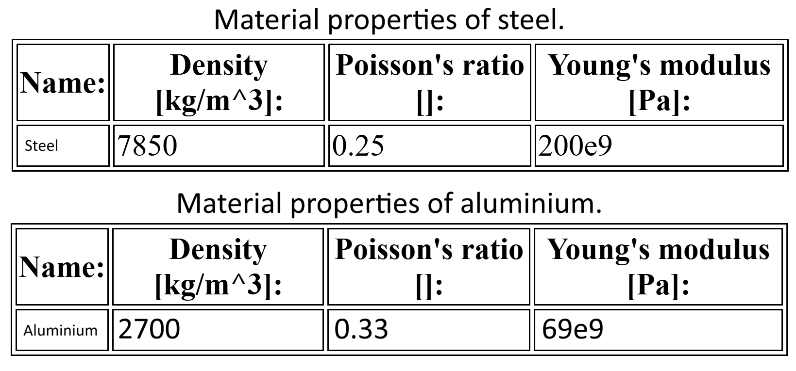
- A material is assigned to the MbD Parts. For this example the average properties of steel were used for the
pendulum, and aluminum was assigned to the pin.
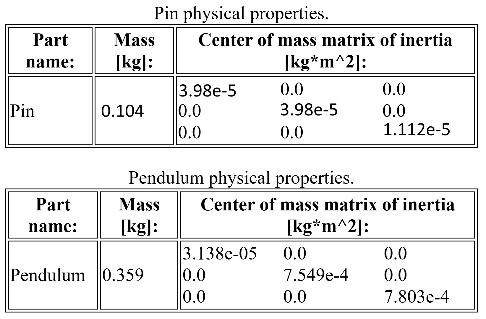
- The mass and mass matrix of inertia of each MbD part are computed using the
volume and the volume matrix of inertia from the CAD solid geometries, along with the material density.
- Gravity is assigned.
- Two markers are attached to the adequate sub-geometry of each part.
- A hinge joint is created using the two markers. This joint is used to solve the assembly
as well as during the MbD simulation stage.
-
The pre-processor automatically generates an input file for the selected MbD solver
(FreeCADMbD).
The images below show the pendulum and pin masses and inertia matrices (left), and the applied
properties of steel and aluminum (right).